How Are Flexible Printed Circuits Manufactured?
Flexible Printed Circuits
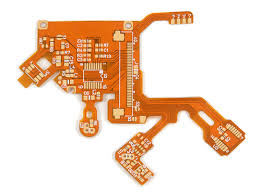
Flexible printed circuits (abbreviated as FPC) have conductive traces on a thin, flexible substrate. They may feature surface-mount devices like resistors and LEDs and have a connector or termination point for integrating with other components. They are found in a variety of products from consumer electronics to medical devices. In order to function properly, the circuit boards need to be manufactured in a precise manner.
The first step of manufacturing a flexible printed circuit is to create copper-plated layers on the substrate film. The conductor width and spacing are determined by the design of the circuit. For example, the width of a single-sided flex circuit is about 375 micrometers. This is an acceptable value, but the width needs to be larger if the circuit will have multiple traces.
Manufacturers use adhesiveless conductive polymer (PI) that adheres to the copper to create a conductor layer. This PI is made of polyimide or other flexible dielectric film that can withstand high temperatures and reflow soldering. It also resists flexing and provides good adhesion. Then, manufacturers screen print the traces on the PI with silver-based ink. They also use a UV light to cure the ink and form a copper pattern.
How Are Flexible Printed Circuits Manufactured?
After the traces are printed, the manufacturing process moves to the etching stage. Etching is a chemical procedure that removes copper from the traces to reveal the circuit pattern. The etching process is critical, because it makes up for any isotropic losses during the manufacturing process. In addition, the etching process exposes drill-hole pads for use in surface-mount applications. The etching process can be influenced by several factors, such as different types of copper, etch masks, and conductors.
Depending on the application, manufacturers can add a service loop to the flex circuits to allow for extending the life of the product. They can also add a shielding layer to protect the traces and connections from electromagnetic interference. Once the etching and silk screening process is complete, manufacturers perform many electrical tests on the finished products to ensure that they are functional.
Before the etch, plated, coverlayed, and blanked flex circuits can be combined with rigid sections to make a hybrid flex-rigid board, they need to be laminated together. This requires the flex circuits to be in place before laminating, and they need to be secured with heat, pressure, and adhesives.
The etched, plated, coverlayed, and unblocked flex circuits are then laminated to the glass-epoxy rigid panels along with their respective copper layer stacks. The flex circuits can be separated into one- or two-layer flex sections. Each flex section will have a maximum copper layer count of 2, which is adequate for most flex-rigid board designs. The flex-rigid boards are then assembled into their final form using more heat, pressure, and adhesives. The result is a functioning, durable hybrid flex-rigid circuit board. For the best results, it is important to choose a quality manufacturer that understands the importance of this complex assembly process.